
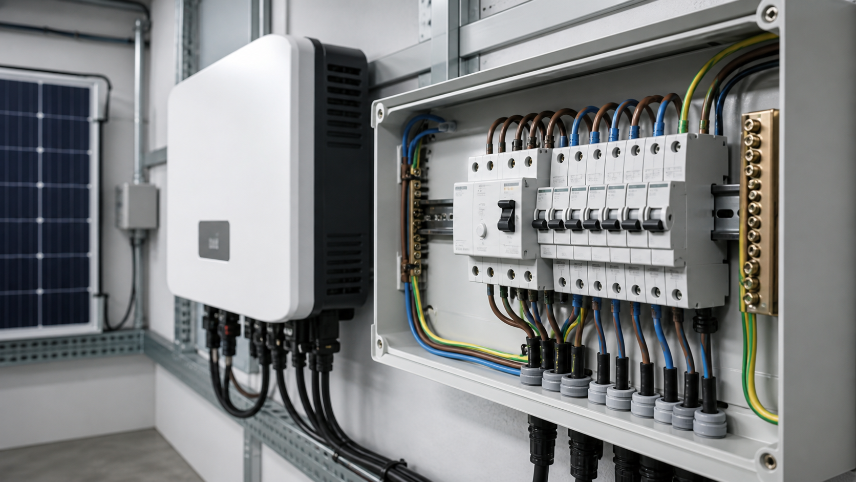
1. Why a standard RCCB is not enough on a PV circuit
A residual current circuit breaker works by summing all live conductors through a toroidal current transformer. In a healthy circuit the vector sum is zero; a leakage path to earth unbalances it, the transformer produces a small output, and the trip unit opens the contacts.
That mechanism depends on an alternating residual current. A transformerless PV inverter can superimpose a smooth, non-alternating DC component on the AC output. A DC component does not change flux in the core, but it does bias the core toward saturation. Once the core is partly saturated, its ability to respond to a genuine AC residual current collapses.
The practical outcome is a device that passes its test button and still fails to protect. This is why the topic appears in installation rules rather than only in product datasheets: earthing and protection provisions for PV installations are addressed in IEC 60364-7-712, which is the clause set most destination markets adopt when they require DC-capable residual current protection downstream of an inverter.
- Blinding effect — DC residual current biases the CT core and suppresses AC sensitivity
- Test button is not proof — it verifies the trip mechanism, not immunity to DC bias
- Inverter topology decides the risk — transformerless designs carry it, isolated designs largely do not
- Check the inverter declaration — many inverters state DC residual current is limited to 6 mA, which permits Type A

2. Type AC, Type A and Type B compared
Residual current device types describe which residual current waveforms the device can detect. They are not quality grades — they are functional classes, and using the wrong class is a compliance failure rather than a performance compromise.
Residual current device classes and their applicability to PV systems.
The decision rule is straightforward. Read the inverter manual. If it declares that DC residual current is limited to 6 mA or less, a Type A device is normally acceptable. If it does not, or if the same distribution board also feeds EV charging or battery storage, specify Type B. Where storage and charging share the board, Type B is usually the safer default regardless of the inverter declaration.
3. The specifications that actually matter
Beyond the type class, five parameters determine whether a device suits the circuit. Getting these right at the specification stage prevents both under-protection and the far more common problem of a system that trips for no visible reason.
- Rated current (In) — must equal or exceed the rating of the upstream protective device. NEUTRON's miniature residual current ranges cover 6, 10, 16, 20, 25, 32, 40, 50 and 63 A; moulded-case residual current breakers extend the range for feeder and main duty.
- Rated residual operating current (IDn) — 30 mA for personnel protection on final circuits, 100 mA or 300 mA for fire protection on feeders and sub-mains. NEUTRON's WSB7L-63 offers 0.03 A, 0.1 A and 0.3 A settings.
- Rated residual non-operating current — should be 0.5 IDn, so a 30 mA device must not trip below 15 mA. This is the parameter that governs nuisance tripping margin.
- Breaking capacity — NEUTRON's DZ47LE-63 and WSB7L-63 ranges provide 6000 A rated ultimate and service short-circuit breaking capacity at 230/400 V, which suits most final and sub-distribution circuits.
- Pole configuration — 1P+N for single-phase final circuits, 2P where both conductors must be isolated, 4P for three-phase supplies. On a three-phase PV connection, 4P is the norm because the neutral must be interrupted.
- Tripping time — verify against the standard curve. NEUTRON's WSB7L-63 trips within 0.1 s at IDn, 0.06 s at 2 IDn and 0.04 s at 5 IDn, with a maximum breaking time of 0.04 s at 500 A.
4. Choosing sensitivity without creating nuisance trips
A PV array is a large capacitive structure. Module frames, DC cabling and inverter EMC filters all create a standing leakage current to earth even when nothing is faulty. On a large commercial array this can reach tens of milliamps, particularly on damp mornings when moisture films raise surface conductivity.
That standing leakage is why a single 30 mA device protecting an entire inverter feeder will trip unpredictably. The correct response is not to raise the sensitivity of one device — it is to split the protection. Use 30 mA devices on the final circuits that genuinely need personnel protection, and a 100 mA or 300 mA time-delayed device upstream for fire protection across the feeder.
Two further measures reduce false operation. First, keep the residual current device downstream of any long, capacitive AC cable run rather than at the far end of it. Second, on installations where an unplanned outage is costly, consider a residual current breaker with adjustable sensitivity and a controlled reclose function. NEUTRON's WCM7EL moulded-case residual current breaker is designed for three-phase four-wire TT systems and offers settable residual operating current of 100, 200, 300, 500 or 800 mA, a 0.06 s time-delayed trip, a configurable reclose interval of 20 to 60 seconds, and an LCD showing three-phase voltage, current and measured leakage.
5. Standards, certification and destination-market checks
Residual current protection is one of the most heavily regulated categories in low-voltage distribution, and the paperwork matters as much as the device. Confirm which standard the device is tested to and which certification the destination market recognises.
Also confirm the environmental envelope. NEUTRON's miniature ranges are rated for -5 C to +40 C ambient, altitude up to 2000 m, pollution degree 3 and installation category III. Outside that envelope — high-altitude plants, unconditioned enclosures in hot climates — derating or a different enclosure strategy is required, and that should be settled at tender stage.
- IEC 61008-1 — residual current operated circuit breakers without integral overcurrent protection (RCCB)
- IEC 61009-1 — residual current operated circuit breakers with integral overcurrent protection (RCBO). NEUTRON's DZ47LE-63 and WSB7L-63 ranges are built to this standard together with GB 16917.1
- IEC 62423 — Type F and Type B residual current devices
- IEC 60364-7-712 — installation requirements for PV supply systems
- IEC 60947-2 Annex B/M — residual current protection integrated with moulded-case circuit breakers
- CE and CB certification for European and CB-scheme markets; CCC for the Chinese domestic market
Technical diagram shown at a readable responsive scale.
6. Procurement mistakes that cost money later
- Ordering Type AC because the price list defaults to it — the saving is a few dollars per pole and the exposure is a non-compliant installation.
- Assuming Type B everywhere — Type B carries a real cost premium. Where the inverter declares a 6 mA DC residual current limit, Type A is compliant and cheaper.
- Specifying 30 mA on a large feeder — standing capacitive leakage will trip it. Split protection instead.
- Ignoring the non-operating current — a device that trips at 40 percent of IDn will be blamed on the array, not on the device.
- Mixing pole counts across a board — 1P+N and 2P devices are not interchangeable when the neutral must be isolated.
- Buying to a model number without the test report — request the routine test evidence for the batch you are receiving.
- Overlooking storage and EV charging on the same board — both change the residual current waveform and can force a Type B decision.
7. The NEUTRON residual current range and where it fits
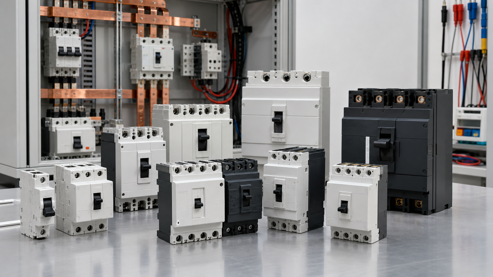
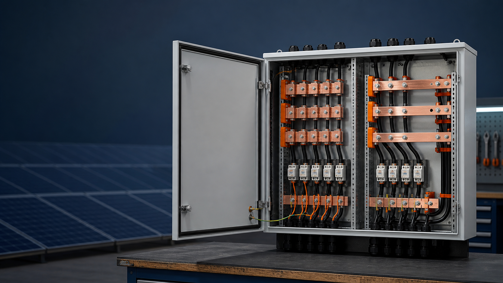
NEUTRON manufactures residual current protection across the miniature and moulded-case ranges, and builds the low-voltage assemblies that house them, which allows the protection scheme and the enclosure to be coordinated in one order.
On the miniature side, the DZ47LE-63 series covers AC 50/60 Hz circuits at 230/400 V up to 63 A with combined leakage, overload and short-circuit protection, built to IEC 61009-1 and GB 16917.1 with 6000 A breaking capacity. The WSB7L-63 series covers 6 to 63 A at 230 V in 1P+N with residual settings of 0.03, 0.1 and 0.3 A, 6000 A ultimate and service breaking capacity, and non-operating current at 0.5 IDn. The WSB9LE ranges extend the frame size to 125 A.
On the moulded-case side, the WCM1L and WCM30L residual current breakers cover feeder duty, while the WCM7EL adds microprocessor control, settable residual current, selective time delay, overvoltage and undervoltage delay protection, metering display and selective auto-reclose for three-phase four-wire TT networks. Where a project needs Type B performance, NEUTRON integrates a specified Type B device into the assembly and builds the board to IEC 61439 around it.
Supporting devices come from the same catalogue: WSH7-100 and WH1-125 isolators for safe disconnection, and WCU8 surge protective modules for the AC side of the inverter connection.
8. Safety and limitations
Residual current protection reduces the risk of electric shock and earth-fault fire. It does not protect against a line-to-neutral fault, it does not replace overcurrent protection, and it does not compensate for a defective earthing arrangement.
Selection must be confirmed by the responsible design engineer against the earthing system in use (TT, TN-S or TN-C-S), the inverter's declared DC residual current behaviour, and the wiring rules of the destination market. Devices must be functionally tested at commissioning and periodically thereafter.
This is general technical guidance, not a substitute for local electrical code, the applicable standard, product datasheets or a qualified engineer's design review. Confirm ratings and final configurations against the actual project.
Bring the project inputs to the first review.
NEUTRON can review the application context, electrical envelope, enclosure conditions and document requirements related to comprehensive buying guide for pv system rccbs: ensuring safety and compliance before quotation.
Discuss a technical requirementContinue learning
Explore related technical guidance in Solar PV.
Converted from the approved Period 01 source article for Comprehensive Buying Guide for PV System RCCBs: Ensuring Safety and Compliance. Editorial instructions, duplicate anchor placeholders and embedded publishing directions were removed; the technical body is retained for educational use.